12V DC - White Paper
12-24V DC Moodifier LED Lighting Installation - White Paper
Illustrated as a small apartment, summer cottage, motorhome or boat
Six smart 12-24V DC LED lighting applications applied in four rooms.
Controllable with standard wall switches and over the Internet using any web browser.
This white paper is targeted for a basic living space with a kitchen, living room, one bed room and a bath room. This type of small living area can be covered by one single Moodifier Constant Voltage Driver and works very well for an illustration. If you need to cover a larger living space with more rooms you can simply expand the installation by adding another Constant Voltage Driver or a Constant Voltage Slave. Each added unit will give you twice as many lighting applications and light outputs.
Since Moodifier is a 12-24V low voltage control system you do not need a certified electrician to perform the installation, anyone who has the electrical knowledge to understand how to do the wiring can perform the installation.
This white paper illustrates 12V DC, but works just the same for 24V DC.
1) System overview with wiring diagram
Lets start by looking at a wiring diagram of the installation. It provides a clear view of everything that is included and how it is all wired up to the Moodifier Constant Voltage Driver.
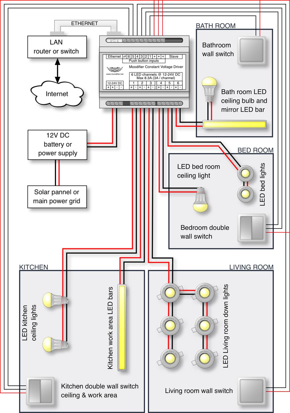
As you can se in the wiring diagram, there are 4 rooms, a kitchen, a living room, a bed room and a bath room. Cables go from the Moodifier Constant Voltage Driver to every light and wall switch in each room, but they are not pulled out as pictured in the wiring diagram. In reality you would pull out one flex tube from the Moodifier Constant Voltage Driver to each of the rooms, and in that flex tube you would pull all the cabling that is used in each room. So for this installation you would have 4 flex tubes going from the Moodifier unit to each room.
Lets continue to look at what the flex tubes and cabling would look like in reality for each of the rooms.
2) Pulling out cables and wiring
Bath room and living room
Lets begin by looking at how to pull the cabling to the bath room and living room. They both have one wall switch that controls one light application per room (one individually controllable light functionality within the room).Lets focus on the bath room, it has two LED lights, one ceiling mounted 12V LED E27 bulb and one 12V LED bar (LED strip) that work together, controlled by a single wall switch.
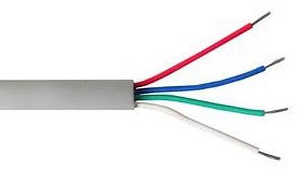 The wall switch requires 2 thin wires (+ and -). A standard copper telephone cable with a wire diameter of 0,5 mm (AWG 24) is very well suited for this purpose. Telephone cables usually come with 2, 4 or 6 wires. You can use a telephone cable with any number of wires or even an Ethernet cable with 8 wires, the important thing for this bath room is that it has at least 2 wires.
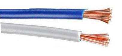 The two LED lights that will be connected will also require 2 wires (12V DC + and -). A standard electrical copper cable with a wire area of 1.5 mm² (AWG 15-16) is very well suited for this purpose. Remember to choose wire insulation colors that let you identify and separate the 2 wires.
 It is always a good practise to place all cables and wires in a flex tube, that will let you easily replace them in case something is broken or you accidentally put a screw or nail through one of the cables.
All in all the bath room will require one flex tube containing a 2-wire tele cable and two 1,5 mm² electrical wires. Remember to choose a flex tube that is wide enough to fit the cables.
Start by pulling out the flex tube from the Moodifier unit to the closest connection point in the bath room, we assume it is where the E27 LED bulb will be. Then, from that connection point pull out a flex tube from the first connection point to the other two connection points in the bath room.
Once the flex tubes are in place you simply pull the tele cable and the two electrical wires through the flex tube from the Moodifier unit end out to the first connection point in the bath room.
If the first connection point is at the ceiling E27 bulb, you will then need to pull the tele cable through the second flex tube to where the wall switch connection point is. You will then also need to pull the two electrical wires through the third flex tube to the LED bar connection point. Make sure to pull out an extra loop of electrical wire at the first connection point, enough to comfortably be able to connect the E27 LED bulb and the LED bar in parallel.
Repeat the process with exactly the same methodology and cabling for the living room.
Kitchen and bed room
The kitchen and bed room has two separate light applications each (two individually controllable light functionalities within the same room). This will require a few more wires in the flex tube.
Both the kitchen and bed room have a two button wall switch, each button controls a separate light application. These wall switches requires at least 3 thin signal cables (+ and two -). Again, a 4-wire standard copper tele cable with a wire diameter of 0,5 mm (AWG 24) is very well suited for this purpose.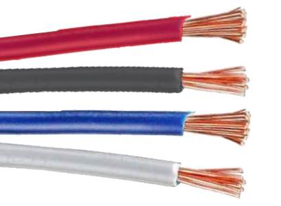 The kitchen and bed room both have two separate light applications. Each light application requires 2 separate electrical cables (12V DC + and -). Again, a standard electrical copper cable with a wire area of 1.5 mm² (AWG 15-16) is very well suited for this purpose. Remember to choose wire insulation colors that let you identify and separate each of the 4 electrical wires at both ends of the flex tube.
Start by pulling out a flex tube from the Moodifier unit to the closest connection point in the kitchen and the bed room. Then, from those connection points pull out flex tubes to the other connection points in each room.
The kitchen and bed room both have two separate light applications. Each light application requires 2 separate electrical cables (12V DC + and -). Again, a standard electrical copper cable with a wire area of 1.5 mm² (AWG 15-16) is very well suited for this purpose. Remember to choose wire insulation colors that let you identify and separate each of the 4 electrical wires at both ends of the flex tube.
Start by pulling out a flex tube from the Moodifier unit to the closest connection point in the kitchen and the bed room. Then, from those connection points pull out flex tubes to the other connection points in each room.Once the flex tubes are in place you simply pull the tele cable and the four electrical wires through the flex tube from the Moodifier unit out to the first connection point in the kitchen and bed room.
From there you continue to pull the tele cable to the wall switch connection point, and both pairs of electrical cable to each light application connection point and proceed to any additional connection points of each light application.
Let's continue by looking at how the wall switches are connected and how they work.
3) Wall switch wiring and operation
You can use any type of wall switch with a momentarily circuit closing push button (when the button is pushed in, the circuit closes "door bell style"). Very simple and easy to install.
The inputs of the Moodifier unit are triggered by closing a circuit between any of the + connectors to the input channels of the unit.
A short push on a button activates or de-activates the lights depending in what state they are in. Holding in the push button will slowly dim the lights up and down 0-100%. Have you ever heard of "on/off push dim" functionality, well that is what it's called.
The dual button wall switches that are in the kitchen and bed room operate in the exact same way. The only difference is that the wall switch has two momentarily closing buttons instead of one, each closing a circuit to a different input on the Moodifier unit.
4) Connecting and wiring up the LED lights
Connecting the lights is pretty straight forward. Connect the + and - wires of the lights to the + and - wires coming from the Moodifier Constant Voltage unit. Multiple lights should be connected in parallel.
5) Connect the Moodifier unit
Once all the wall switches and lights are connected to the wires in each room it is time to connect the other end of the wires to the Moodifier Constant Voltage unit. Each of the 4 flex tubes coming to the Moodifier unit has wall switch and light wires that you simply connect to the input and output connectors on the unit. Make sure to not mix up the + and - cables, doing so can destroy the lights and or Moodifier unit.
When you have double checked that all wires ar properly connected to the right connector you it is time to connect the power to the Moodifier unit. The power can be a 12V power supply, a 12V battery connected to solar panels or any other 12V DC power source you like. Either way, the power source will have a 12V DC + and - cable that you simply connect to the + and - power connectors of the Moodifier unit. MAKE SURE TO NOT MIX UP THE + AND - CONNECTIONS since doing so can destroy the Moodifier unit and/or the lights.
Once the power is turned on you can connect the unit to your network with a standard Ethernet cable and start to use any of the Moodifier softwares to further configure and control your 12V DC Moodifier lighting and power control solution.